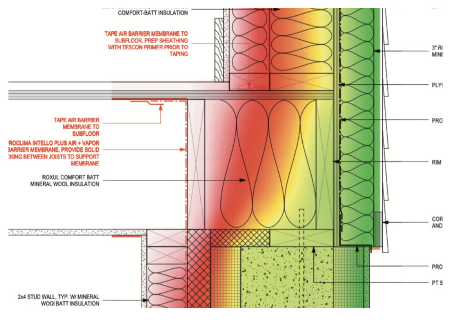
Preparing details for thermal analysis.
To verify envelope performance for Passive House certification, BLDGTYP runs a series of thermal simulations of a project's typical assemblies and its critical junctions. Those simulations only work if the design team hands off clean CAD base-files. This guide explains exactly what to draw, how much, and how to format the drawings so the models are accurate the first time.
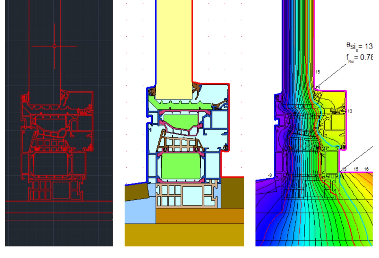
Why we need base-files.
To verify and demonstrate envelope performance for Passive House certification, BLDGTYP executes a series of thermal simulations of: (a) all "typical" building assemblies for walls, roofs, and floors; and (b) all detail thermal bridging at critical junctions between two envelope elements, such as where the roof connects to the wall.
To run these simulations, the design team prepares base-files and transmits them to BLDGTYP. These flat 2D CAD drawings are imported into our simulation environment, which we use to evaluate:
- R-values of all assemblies
- Psi-values of all critical junctions
- Critical interior surface temperatures for durability
This guide explains how to prepare the required base-files.
// Reference documents: all thermal-bridge models follow the protocols in ISO 10211 ("Thermal bridges in building construction"), ISO 13788 ("Hygrothermal performance of building components and building elements"), and ISO 10077-2 ("Thermal performance of windows, doors and shutters"). See these references for detail on any specific requirement.
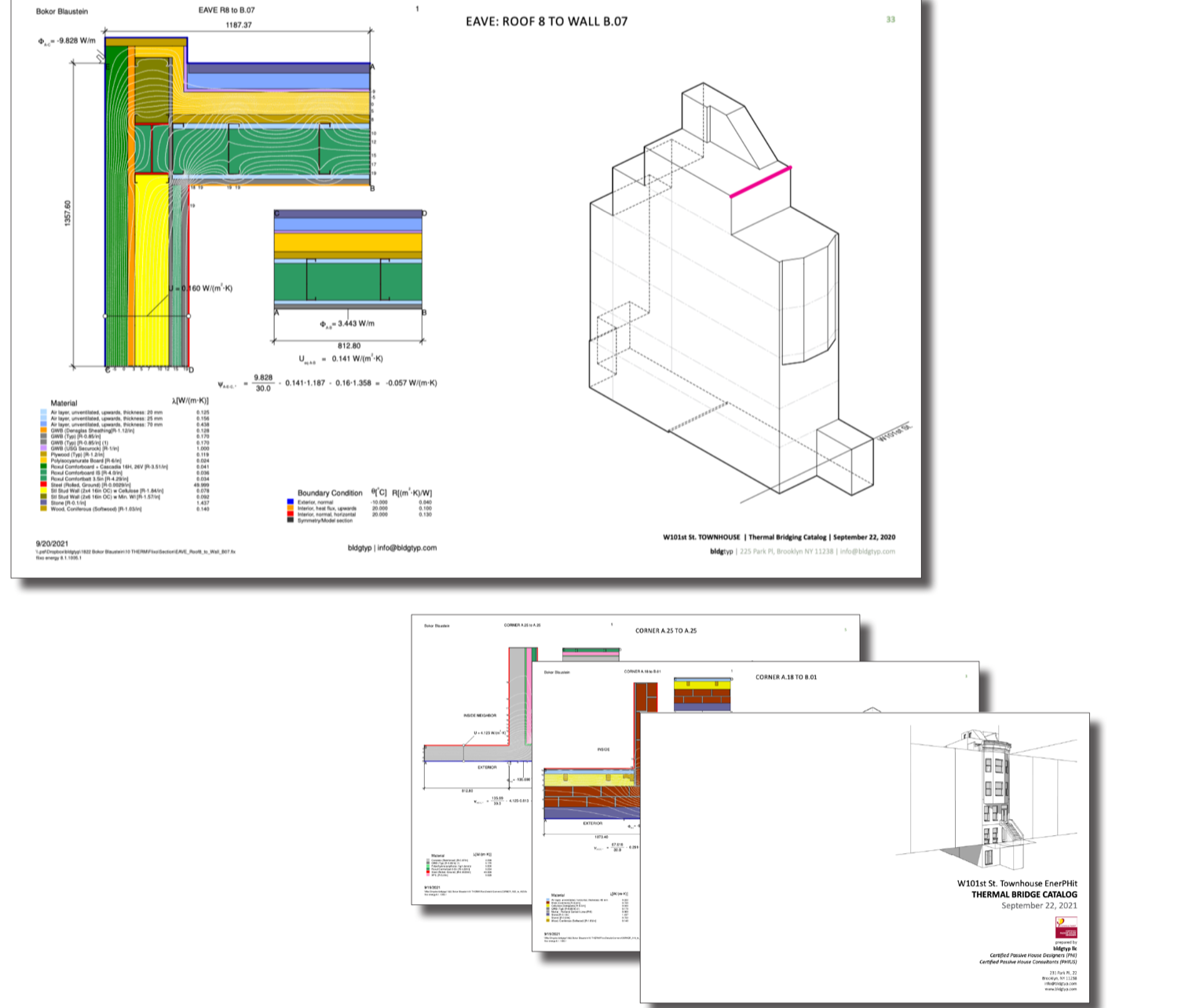
Every detail lands in the catalog.
As part of the Passive House certification submission, BLDGTYP builds a project detail "catalog" that collects and organizes all the key project details alongside their thermal-analysis results. This catalog is a central piece of the certification review.
It is the design team's responsibility to provide accurate details so BLDGTYP can produce the catalog and the required simulations. All detail geometry, material specifications, and any special considerations should be communicated to BLDGTYP so the project details are clean and consistent for the certification reviewers.
All details in the catalog must match the as-built conditions as closely as possible, and are coordinated with the whole-building energy model.
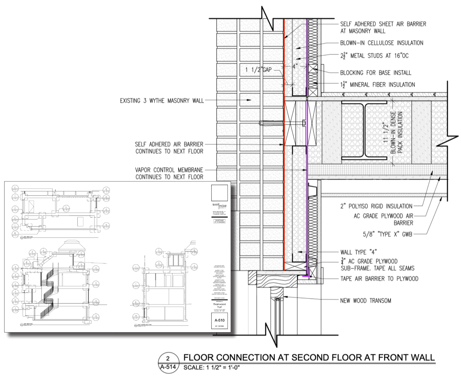
What each detail must show.
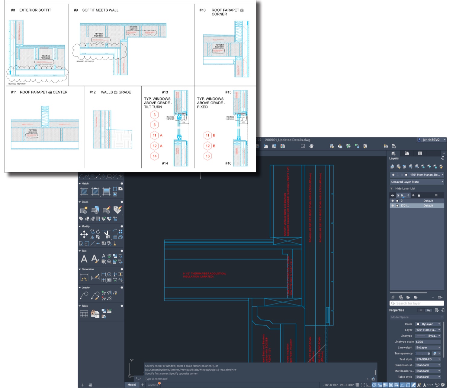
Each project detail and assembly must be documented in the architectural drawing set in a way that lets the detail catalog reference it — typically a separate drawing for each relevant detail. To allow for Passive House certification review, every detail should clearly illustrate:
- All insulation layers and materials used as part of the envelope.
- All structural and bridging elements — studs, beams, shelf angles, or anything else penetrating the insulation — with their material designations / product information.
- All air-tightness layers and materials.
- All moisture / vapor-control layers and materials.
- All exterior waterproofing.
How to prepare the CAD.
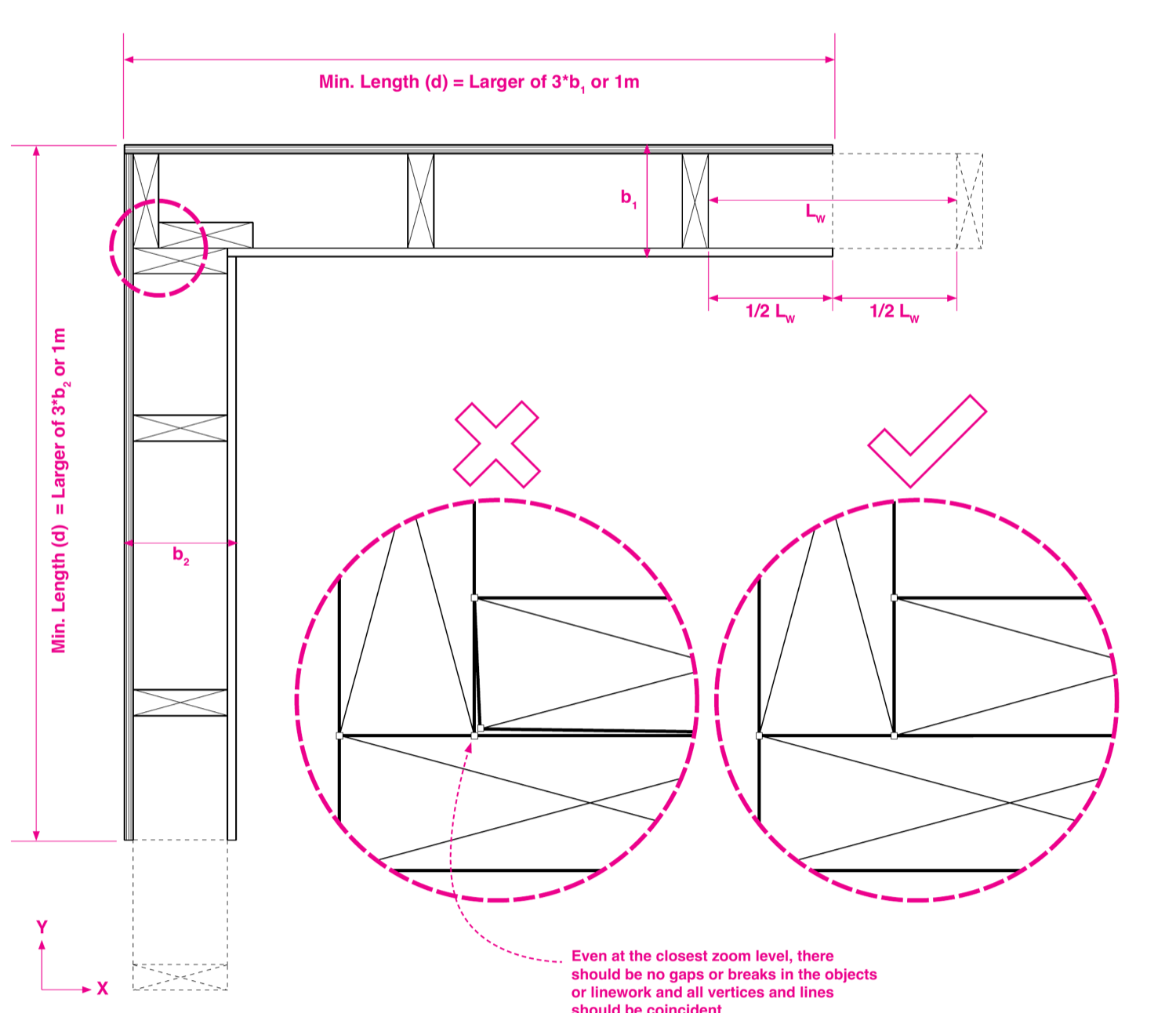
All drawings should be full scale and delivered in CAD format (DXF or DWG). Take care that the drawing is flat (no 3D elements) and that all hatches, dimensions, and notes are removed or placed on dedicated layers, separate from the basic geometry profiles. Groups, blocks, and other dynamic objects should be un-grouped, broken into raw geometry, and flattened. All objects to be simulated must be drawn as closed polygons, with every vertex overlapping or touching — no gaps or breaks in the lines or objects.
Multiple details / assemblies may be supplied in a single CAD file if preferred, provided the different details do not touch or overlap and it is clear how they are organized within the file.
If needed, notes or other reference information may be added to the "Defpoints" layer to communicate information to the thermal modeler or to name / catalog the details.
How much to draw at a junction.
Per ISO 10211, for all junctions — corners, parapets, and the like — the minimum dimension (d) is 1m in both directions (x and y). In addition, length (d) should be at least 3× the thickness (b) of the assembly. If the assembly includes repeating thermal bridges (studs), extend the drawing beyond the minimum to include half the length of a typical stud/joist bay (Lw). Any assembly may be drawn larger than the minimum if desired.
What if your wall isn't actually 1m long? Even if windows, doors, or other elements sit closer than 1m to the corner, omit those elements here. Draw only the "typical" assembly and the structural items (columns, beams) related to the corner or intersection under investigation. Those additional disruptions (window jack studs, etc.) are calculated separately and included in the energy model as their own thermal bridges.
And remember: all objects to be simulated should be drawn as closed polygons, with every vertex overlapping or touching — no gaps or breaks.
How much to draw for R-value.
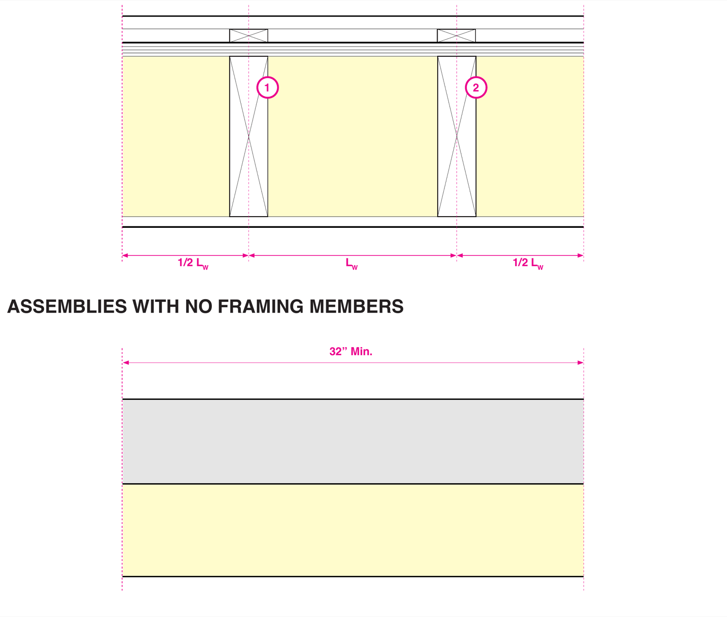
To properly assess assembly R-values, we simulate the effective R-value of each assembly, including all material layers, framing elements, and finish surfaces — including battens and air layers.
For each "typical" assembly in the building (walls, floors, roofs), the drawing should be long enough to include at least two typical framing elements (studs, joists, etc.). If no repeating elements are present — as in a cast-in-place concrete slab — the drawing should be a minimum of 32″ long.
Where thermal bridges hide.
Details to be assessed for thermal bridging include, but are not always limited to, any area where the envelope changes direction by more than 60°, any area where the thickness of the primary insulation layer changes, and any area where the material conductivity of the insulation layer shifts because of bridging elements or a change in material type. If you're unsure whether a detail needs to be drawn and simulated, let us know and we'll review it together.
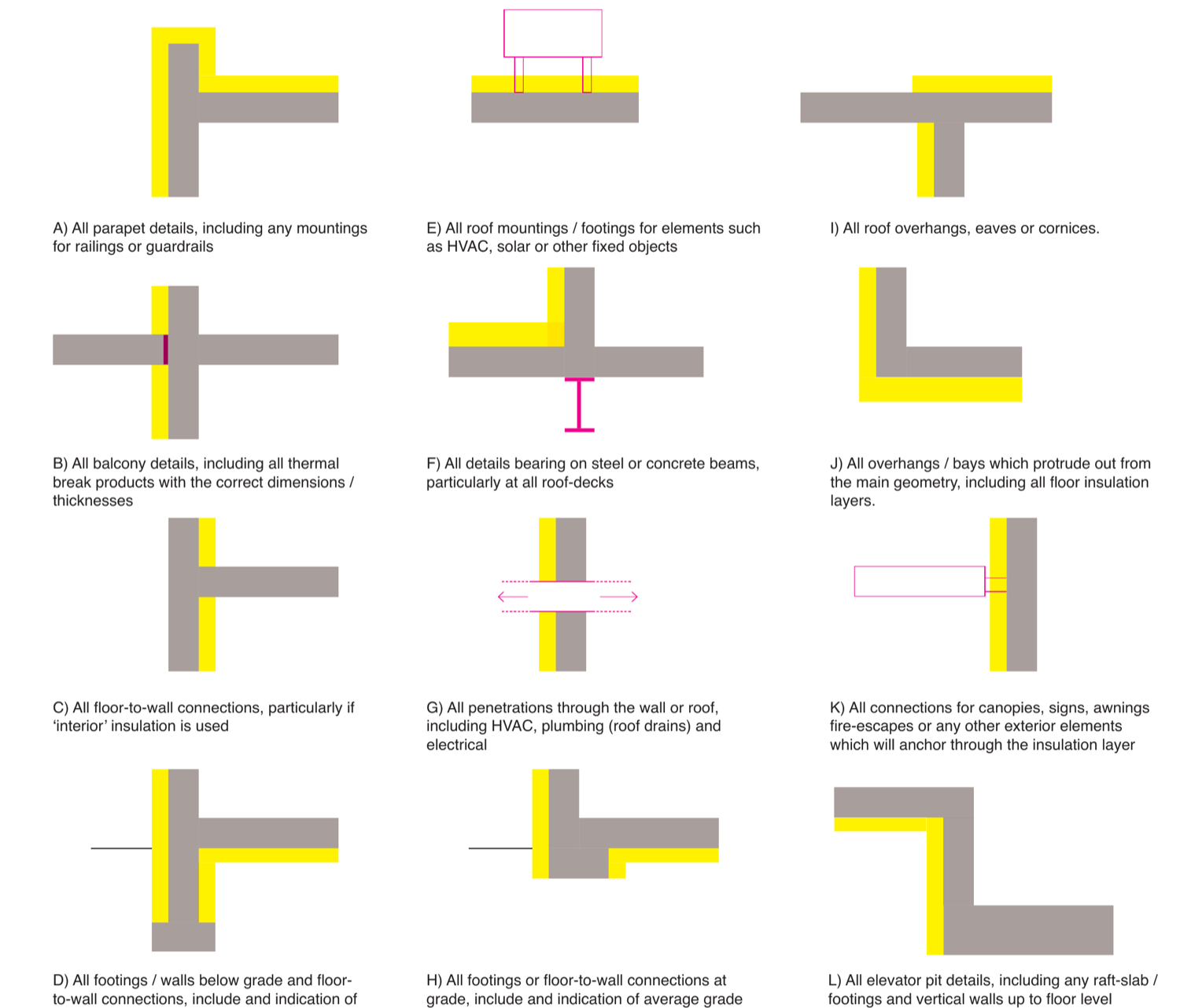
- AAll parapet details, including any mountings for railings or guardrails.
- BAll balcony details, including thermal-break products with correct dimensions / thicknesses.
- CAll floor-to-wall connections, particularly where "interior" insulation is used.
- DAll footings / walls below grade and floor-to-wall connections; indicate average grade level relative to floor.
- EAll roof mountings / footings for elements such as HVAC, solar, or other fixed objects.
- FAll details bearing on steel or concrete beams, particularly at roof decks.
- GAll penetrations through the wall or roof, including HVAC, plumbing (roof drains), and electrical.
- HAll footings or floor-to-wall connections at grade; indicate average grade level relative to floor.
- IAll roof overhangs, eaves, or cornices.
- JAll overhangs / bays that protrude from the main geometry, including all floor insulation layers.
- KAll connections for canopies, signs, awnings, fire escapes, or other exterior elements that anchor through the insulation.
- LAll elevator-pit details, including any raft-slab / footings and vertical walls up to floor level.
A special case.
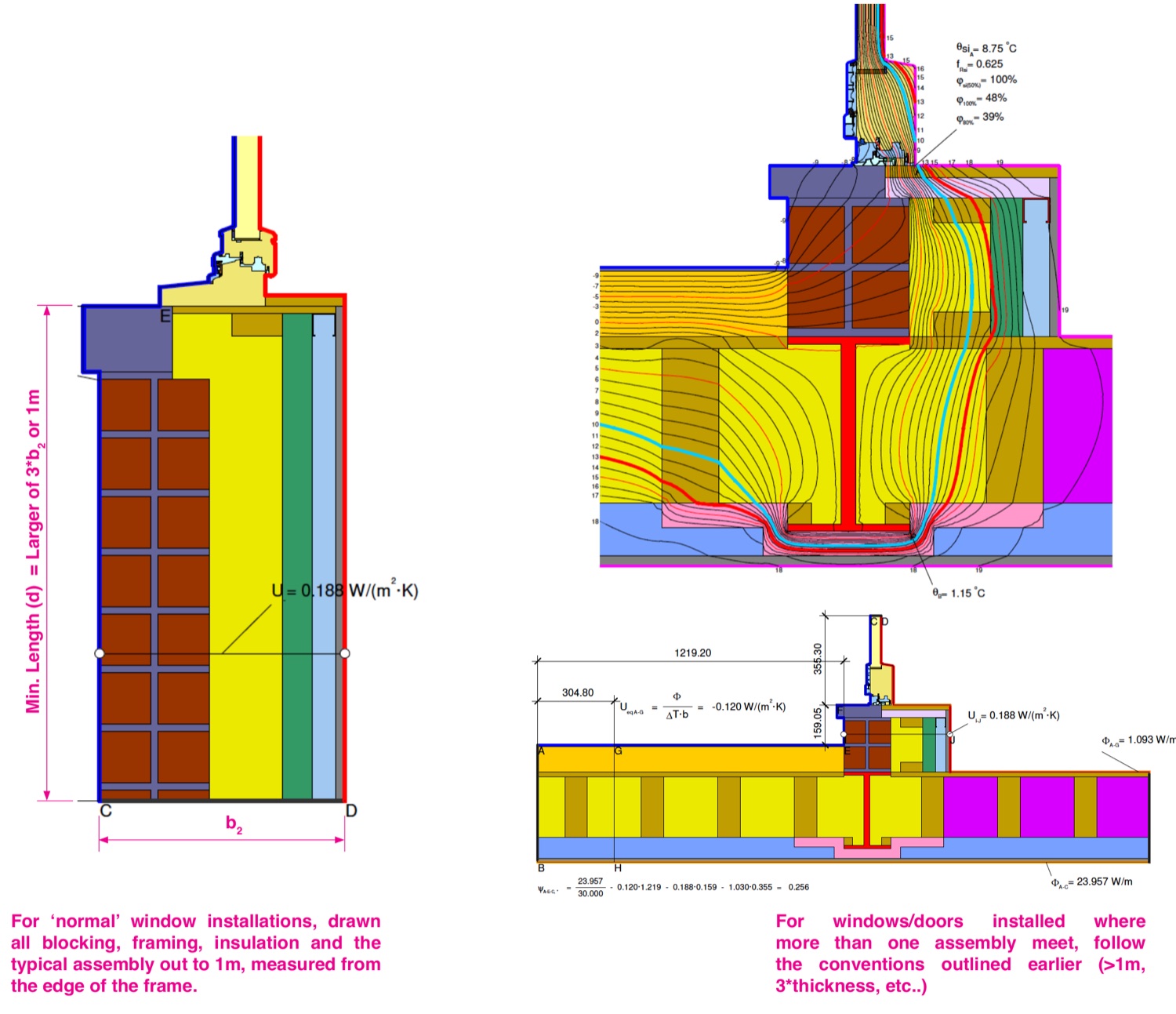
Windows demand even more careful attention than typical assemblies or construction junctions. For each unique window type, CAD base-files are required for the head, sill, and jamb details. A unit with multiple frame configurations (e.g. a simulated double-hung with two different jamb configurations) may need more than one CAD detail. This includes all doors — and door thresholds in particular, which are often critical for condensation risk.
Even if multiple windows share an identical frame type, if they are installed differently or in distinct assemblies, each should have its own base-files and detail set.
Window details should include all blocking, framing, trim insulation, and other elements that support and are part of the installation. Draw the frames accurately with the correct profile, and note that sills and jambs are often different from head profiles — especially for doors and sliding units. Where a window or door is installed at the junction of more than one assembly element (such as a roof deck), draw those elements following the dimension conventions above (>1m, 3×thickness, etc.).
Have details that need thermal-bridge modeling?
Send us your detail set and we'll identify which junctions need simulation and how to prepare the base-files. See our thermal-bridge modeling and NYC 2025 energy-code pages for more.
Get in touch → info@buildingtype.com