Fresh-Air Ventilation

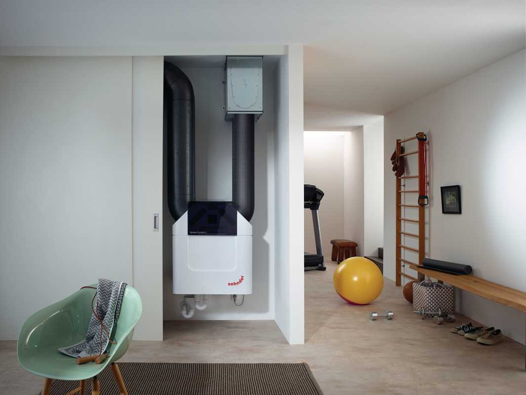
An air-tight, low-energy building in this climate should include dedicated mechanical ventilation with heat-recovery in order to deliver enough fresh air for good indoor air-quality (IAQ) in all seasons.

Supply fresh air to bedrooms and living spaces, extract from kitchens 
                 and bathrooms. Allow for a transfer pathway between zones.


It is important not to over-ventilate a building in winter, otherwise over-dry indoor air and associated health concerns can result. 
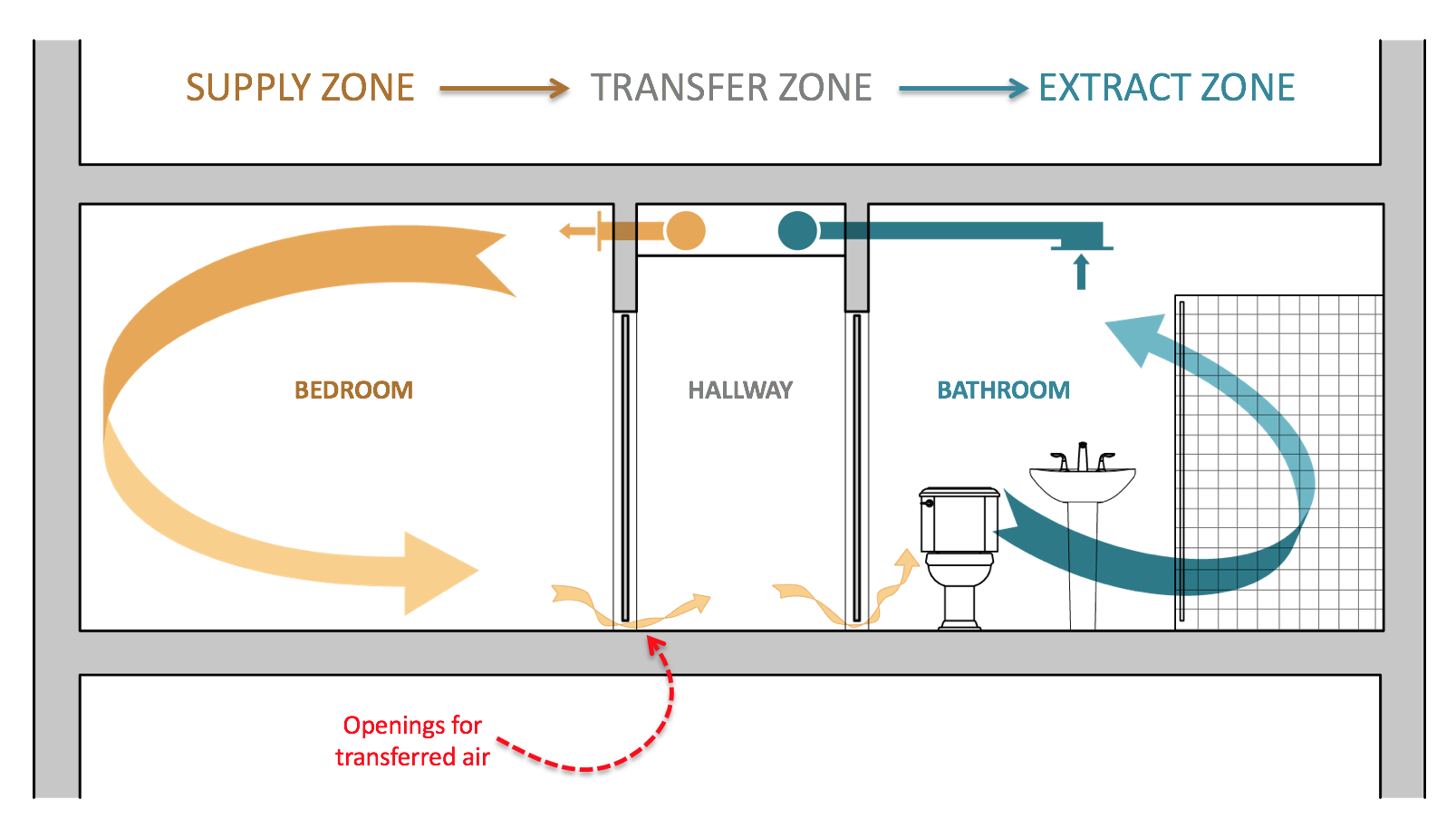
In order to help reduce airflow rates while still maintaining 
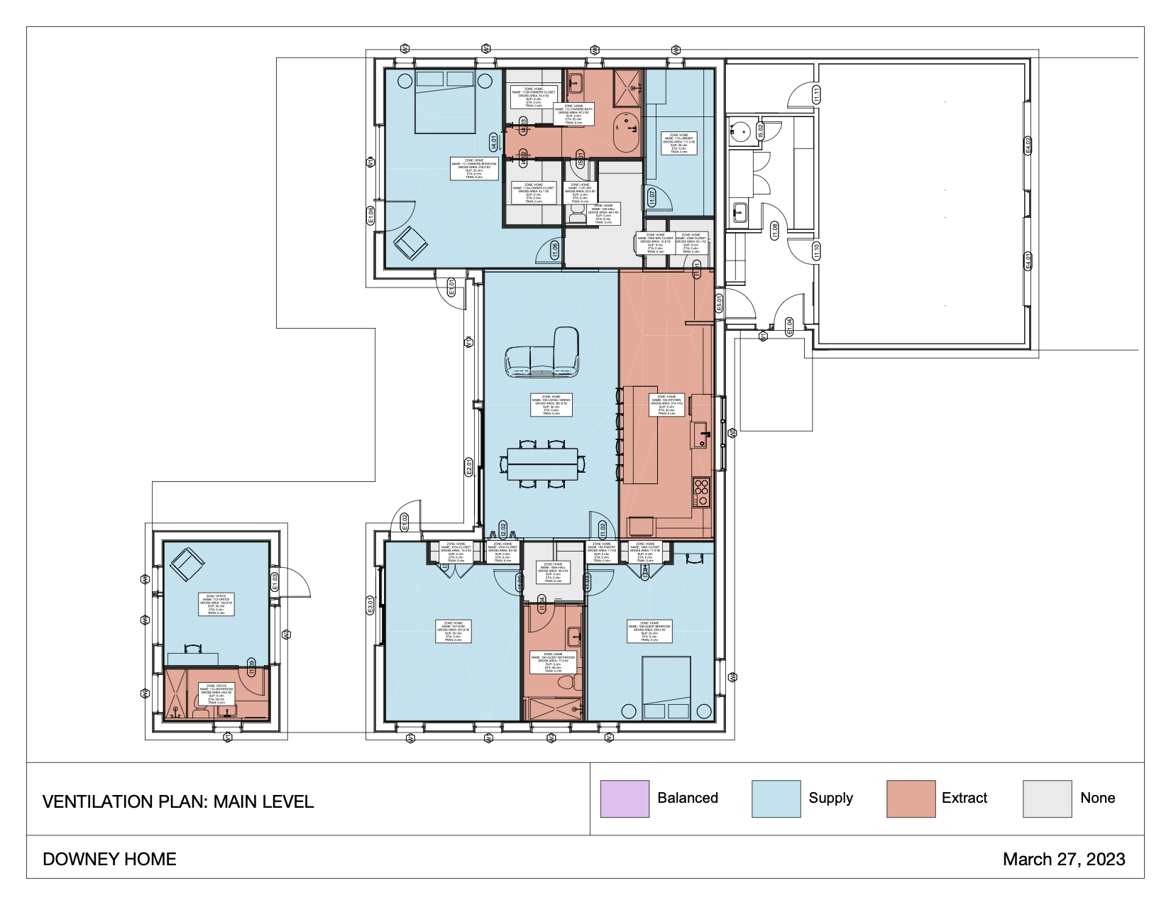
good indoor air-quality, we recommend using a Supply- Transfer-Extract configuration rather than supplying and extracting from each individual room. Supply air should be provided to bedrooms and living spaces, while extract air should be drawn from bathrooms, the kitchen, and any storage spaces. Transfer openings (door undercuts, transfer grills, etc...) should be provided between supply and exhaust spaces.

This configuration reduces the potential for any duct-born sound transmission between spaces, ensures a good mixing of the fresh air supply, and reduces the size, complexity and cost of the ducting required.


Fresh-Air Ventilation Flow Rates

In order to establish good airflow rates for the building which both provide sufficient fresh-air but do not over-ventilate, we recommend a three-part test for sizing fresh air ventilation flow-rates to individual spaces. The larger of the three resultant flow-rates should be used as the design flow rate when selecting an appropriate E/HRV model.

  1. Test for Minimum Supply air flow rate:
    Flow rates should be based on a standard 18 cfm/person occupancy. The occupancy is based on a 'typical' 375 sf/person rate unless otherwise specified. This flow rate is designed to provide good indoor air-quality without causing excessive energy-loss or over-dry air (winter) or excess humidity (summer).
  2. Test for Minimum Extract air flow rate:
    Based on the space usage (Kitchen, Bath, Storage, etc..) establish minimum extract rates. These rates should be as follows: 36 cfm/ kitchen, 26 cfm/full bathroom, 12 cfm/storage or utility room.
  3. Test for a Minimum whole-building ACH @ 100% fan speed:
    The minimum flow rate for any building should be 0.39 ACH in winter at 100% HRV fan speed. This is for hygienic reasons, even if the occupancy or space usage would lead to a smaller flow-rate this minimum takes precedence.

The largest of the above values should be used in order to establish target design flow-rates for the building. We have evaluated the building using this method and recommend fresh-air flow rates according to the schedule below.


Fresh-Air Ventilation System Target Flow Rates


Fresh-Air Ventilation System Diagram | Main Level


Ventilation Floor Plan - Main_Level

Ventilation Components

Zehnder ERV installed on a rooftop

ERV UNIT

For this building, we recommend a centralized high-performance H/ERV unit with better than 75% heat recovery. The Zehnder ComfoAir Q600 ERV would be a good selection and provide excellent Indoor Air Quality while minimizing energy consumption and heat loss. These units are outfit with excellent air filtration (MERV 13) by default which will be critical to ensuring clean and healthy indoor air.

SYSTEM BALANCING


Prior to occupancy, the fresh-air system should be tested and balanced to ensure good air mixing and adequate supply to all living spaces. The HRV vendor should provide this balancing as part of their services.

ERV airflow testing use an anemometer ERV ducting damper element

Image Source: http://www.greenbuildingadvisor.com/blogs/dept/ energy-solutions/commissioning-our-heat-recovery-ventilator Alex Wilson, BuildingGreen, Inc


Phius Ventilation Requirements

In addition to the modeled performance thresholds, in order to certify a building as a Phius CORE, projects must comply with the following design, as per Phius Certification Guidebook v3.02 :

Mandatory Requirements

  1. A whole-building mechanical ventilation system is required to be installed.
  2. The system shall have at least one supply or exhaust fan with associated ducts and controls. Local exhaust fans can be part of a whole-house ventilation system.
  3. The ventilation system must meet one of the following requirements for balance:
    • Total measured supply and exhaust airflows are within 10% of each other. (Use the higher number as the basis of the percentage difference.)
    • The total net pressurization or depressurization from the un-balanced ventilation system does not exceed 5 Pa. The net pressurization/depressurization that the ventilation system imbalance causes on the building is determined using the multipoint air-tightness test results graph.
    • If the exhaust or supply air flow exceeds the exhaust air flow by more than 10%, the energy penalty must be accounted for per Section 6, Energy Modeling Protocol.
  4. HVAC design, installation, testing, and commissioning [ENERGY STAR V3 National Program Guideline] checklist items shall be met for all dwelling units within the project, while HVAC systems for common spaces shall meet the design and commissioning requirements specified by [the Phius] Standard.
  5. 5All [Phius] certified buildings must meet the ENERGY STAR Multifamily High-Rise requirements for lighting and pump motor efficiency shall be met for the entire project.
  6. (I-1.4.3) It is recommended that the ventilation system is capable of at least 0.3 ACH (air changes per hour) based on the net volume at its maximum setting. This is not required.

Ventilation Distribution

  1. All ventilation air inlets located at least 10' ("stretched-string distance") from known contamination sources
  2. All ventilation air inlets located minimum 5' from ventilation exhaust outlet, recommended 10'
  3. Ventilation air comes directly from outdoors, not from adjacent dwelling units, common spaces, garages, crawlspaces, or attics.
  4. Ventilation air comes directly from outdoors, not from adjacent dwelling units, common spaces, garages, crawlspaces, or attics
  5. Outside air passes through a minimum MERV 8 filter prior to distribution, is changed at final and building is ventilated prior to occupancy
  6. Outside air filter is located to facilitate regular service by the occupant and/or building superintendent
  7. Air-sealed, class 1 vapor retarder shall be installed over all air-permeable insulation (such as fiberglass duct wrap) on ventilation ducts connected to outside
  8. Dedicated Fresh Air supply to all bedrooms. Fresh air (OA) supply to bedrooms is required in all dwelling units.
  9. Phius-Rater field-measured bathroom exhaust rates meets one of the following: ≥20cfm continuous or 50 cfm intermittent
  10. Rater-measured kitchen exhaust rates meets one of the following:
    • ≥25cfm continuous,
    • 100cfm intermittent for range hoods
    • 5ACH based on kitchen volume
  11. Total supply and exhaust are within 10% of each other

Ventilation Devices

  1. At final certification, if the exhaust or supply air flow exceeds the exhaust air flow by more than 10%, the energy penalty must be accounted for by de-rating the recovery efficiency of the ventilation equipment based on the unbalanced airflow.
  2. (3.5.2.2) A pre-heater defrost (or ground loop pre-heater) is required for ERVs where the ASHRAE 99.6% design temperature is below the manufacturer’s claimed minimum operating temperature, rather than relying on re-circulation defrost.
  3. If the unit can maintain the required fresh air ventilation rates on average with the unit intermittently in recirculation mode, then this is acceptable. The unit needs to have enough boost to maintain the same time-average fresh air ventilation rate as it would at higher temperatures.

Required Documentation

Mechanical Drawings must show, at minimum:

  1. Ventilation unit and room flow-rates
  2. Duct layout and sizes
  3. Supply and extract airflow rates at each diffuser and the diffuser location
  4. Soundproofing, filters, pressure overflows
  5. Outdoor penetrations for exhaust and supply ducts
  6. Duct insulation thickness and type
  7. Supply and exhaust duct length from the inside of the exterior wall to the ventilation unit
  8. Gross Building Volume Calculation / Justification:
    • Total enclosed volume of the building.
    • Uses exterior dimensions, to the edge of the thermal boundary to calculate.
  9. Net Volume Calculation / Justification:
    • The real interior building volume.
    • Total volume within the building envelope - drywall to drywall, floor to ceiling
    • Same as ventilation volume.

Ventilation Commissioning Requirements:

Will be completed by an approved Phius Certified Rater/Verifier and should include the following information:

  1. Description and location of the project.
  2. Name and address of the Rater/Verifier.
  3. Time and date of commissioning.
  4. Manufacturer and model number of ventilation unit.
  5. Adjusted volumetric flows per diffuser - both supply and exhaust.
  6. Flow comparison between supply and exhaust airstreams as measured between the unit and the exterior, or the interior before any branch ducts (imbalance <10%).
  7. Power draw of the ventilation unit at nominal speed.

Duct leakage testing

  1. Only required for dwelling unit heating and cooling ducts >10’ total system length. It is encouraged that duct testing be conducted at rough-in stage before concealment. Note: RESNET MINHERS Standards requires duct Leakage to Outside to be measured.
  2. Testing to be conducted in accordance with ANSI/RESNET/ICC 380-2019
  3. For ventilation systems, common space systems, and non-residential systems, duct testing may be required by the Energy Star Multifamily New Construction Program. Phius recommends this as a valuable diagnostic tool to ensure proper airflow and balancing can be achieved.

Ventilation System Testing

  1. Room-by-room balancing:
    1. Testing can be performed using devices such as the Retrotec Flow Finder, Energy Conservatory Flowblaster, Energy Conservatory Exhaust Fan Flow Meter (for flows under 35 CFM), Testo 417 (for flows under 100 CFM) with flow straightener and capture hood, CFM-range appropriate non-powered flow hood, and duct tester device with custom capture hood attachment.
    2. Any other device or methodology must be pre-approved by Phius and listed in ANSI/RESENT/ICC Standard 380-2019.
  2. Alternatively, a certified third-party air balancer or product commissioning agent can provide a detailed air balancing report in lieu of the Rater performing this task. A minimum number of airflows are to be verified by the Rater or Verifier per the QA Workbook requirements.
  3. Total ventilation system airflow at unit (supply & exhaust) at maximum speed setting/capacity.
    1. Used to determine if recommended 0.3 ACH can be achieved.
  4. Total ventilation system airflow at unit (supply & exhaust) at typical operation
    1. Total supply and exhaust shall be least 100% of the design values and within 10% of each other.
    2. Individual room supply and exhaust airflows shall be at least 100% of the design values and no more than 10% greater than design values.
      • Note minimum exhaust airflows are mandated per Ventilation requirements outlined in Section 3 of the Guidebook.
    3. Alternatively, measurements of the outdoor air inlet and exhaust outlet of the ventilation system can be made on the exterior of a building using a pressure matching tool such as a duct tester or powered flow hood, so long as:
      • Measurements can be made safely
      • The ducts connecting the system to outside are well sealed
      • Environmental conditions (wind) will not adulterate the test results.
      • Ventilation in/outlets are possible to test without building products or architectural features interfering.
  5. Power consumption measurement recorded in watts for ventilation units in typical 24/7 mode using of the following methods:
    1. Using a power-factor adjusted wattage clamp meter, such as the Amprobe NAV-51, tested at the electrical panel or other accessible location
    2. Using a plug-in watt meter such as the Kill-a-Watt, so long as the system has an electrical plug
    3. Using measured total system airflow or external static pressure and a manufacturer's fan curve table
    4. Alternatively, this may be tested by a third-party balancing firm, HVAC contractor or electrician.
      • Bedrooms shall be pressure balanced to +/- 1 Pa with respect to (WRT) the main body of the [unit] with all other bedroom doors closed and the ventilation system running.

Phius Hot Water Requirements

Phius requires that all buildings certified to the Phius CORE 2021 standard include a high-performance hot-water system which prioritizes energy efficiency and water use reduction. While there are many specific configurations and equipment that can work well on Phius projects, there are certain mandatory requirements that must be followed to achieve certification. To help simplify these requirements, the key Hot-Water design, and testing/commissioning Phius requirements have been summarized in the memo below. These requirements are drawn from:

Mandatory Requirements

  • (6.10.1.1) Phius strongly discourages, but shall not prevent, the use of continuous or time-based hot water circulation systems in multifamily or non-residential projects.
  • An on-site Hot water temperature-rise test is required.
  • If combustion water heating and water heater capacity is less than or equal to 300,000 Btu/h (88 kW) the following are met:
    • A dedicated 240-volt branch circuit with a minimum capacity of 30 amps shall terminate within 3 feet from the water heater and be accessible to the water heater with no obstructions. Both ends of the branch circuit shall be labeled with the words "For Future Heat Pump Water Heater" and be electrically isolated.
    • A condensate drain is installed within 3 feet of the water heater. It is no more than 2 inches higher than the base of the installed water heater and allows natural draining without pump assistance.
    • The water heater is installed in a space with minimum dimensions of 3 feet x 3 feet x 7 feet high.
    • The water heater is installed in a space with a minimum volume of 700 cubic feet or the equivalent of one 16-inch x 24-inch grill to a heated space and one 8-inch duct of no more than 10 feet in length for cool exhaust air.

Program Compliance

All Phius 2021 projects are required to comply with the following programs, including all their specific requirements related hot-water systems.

  • EnergyStar V3
  • EPA WaterSense
    • Maximum pipe volume limitations / time-to-hot
    • On site testing and verification

Required Documentation

Phius certification requires clearly documented equipment and distribution plans for review. Ensure that the plumbing plans include, at a minimum:
Piping:

  • Branch / truck lengths of all piping elements installed
  • Size / diameter of all piping
  • Material of all piping (Copper, PEX, etc..)
  • Insulation type and thickness installed
  • Insulation material data sheets
Tank / Heating Equipment
  • Locations clearly indicated on plumbing plans
  • Make / model / size clearly indicated in all plumbing schedules
  • Product specification sheets for all equipment installed
  • Any additional pumps or circulators, as well as controls

Note: Phius provides “sample” drawings for reference. See following for example: http://www.bldgtyp.com/Phius_examples/Example_Plumbing.pdf


Building Monitoring

Environmental Monitoring


There are several systems available for monitoring the temp, RH, CO2 and other environmental conditions. We strongly recommend installing a system of some form in order to successfully commission the building and correct any issues with indoor comfort over the first year. Environmental monitoring systems are relatively low cost, and we recommend 2 possible systems, the Wireless Sensor Tag by Cao Gadgets LLC, and the Netatmo weather-station. Both systems upload data to the internet over a wireless network and data can be accessed online. (Note: this requires a wireless network to be in operation at the building at all times)

The Wireless Tag system is less costly, but can not monitor CO2, and for this reason we would prefer the Netatmo system.

More information can be found at:
WirelessTag.net
www.Netatmo.com

Netatmo monitoring unit

Energy Monitoring

To really understand a building's energy use, a branch circuit monitoring system is the way to go. Systems such as the Curb energy monitor and the eGauge provide customizable, real-time monitoring of electrical usage. The web/app based interface displays detailed information about the building's energy usage and can help to fine-tune energy conservation measures.

More information can be found at:
EnergyCurb.com
egauge.net.

Curb energy monitoring system
eGauge energy monitoring dashboard example Curb energy monitoring dashboard example